
Outdoor & Industrial UPS
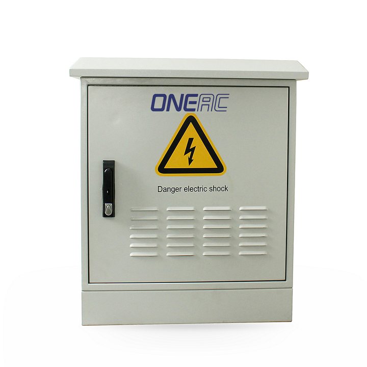
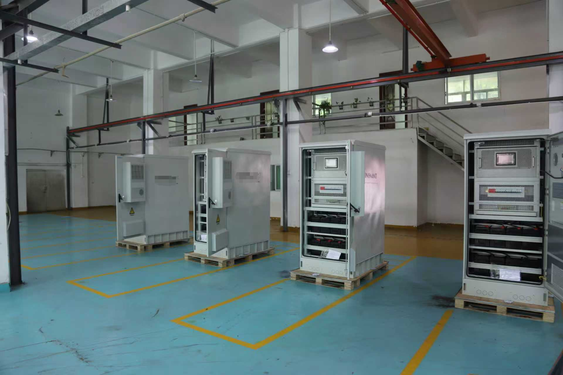
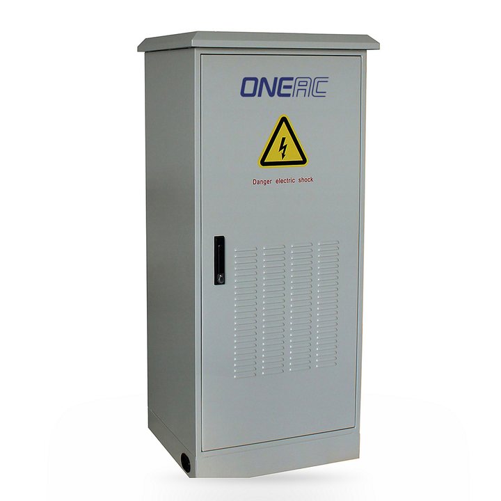
IP65 3 Phases Outdoor Rugged waterproof 10-100KVA industrial UPS
100 kVAIP65 ratedThree phase
True IP65 Waterproof & Dustproof - No external cabinet needed; direct outdoor installation in rain, snow, dust, or high-humidity areas.
Specifications
| Model | 10 KVA | 15KVA | 20KVA | 30KVA | 40KVA | 60KVA | 80KVA | 100KVA |
|---|---|---|---|---|---|---|---|---|
| Capacity | 10KVA | 15KVA | 20KVA | 30KVA | 40KVA | 60KVA | 80KVA | 100KVA |
| System parameters | ||||||||
| Relationship between output power factor cosφ and the load | ||||||||
| 0 . 5 ~ 0 . 8 inductive load | 100% | |||||||
| 0 . 8 ~ 1 . 0 inductive load | 100 ~ 8 0 % | |||||||
| 1 . 0 linear Load | 80% | |||||||
| 0 . 8 ~ 1 . 0 capacitive load | 80% | |||||||
| 0 . 5 ~ 0 . 8 capacitive load | 70% | |||||||
| Computer load | 80% | |||||||
| Overall efficiency (normal mode) Load 100% | 92% | |||||||
| 50% load | 90% | |||||||
| Overall efficiency (economic model): 100% load | 98% | |||||||
| Max. leakage current ( m A ) | 100 | |||||||
| Standby economy mode | Standard function | |||||||
| Mean time between failure( M T B F ) | 200 , 000hours | |||||||
| Computer monitoring interface | Standard configuration R S 232, R S 485 / MOD B U S | |||||||
| Operating temperature | 0 ~ 40 ° C | |||||||
| Max relative humidity | 95 % ( non-condensing ) | |||||||
| Cooling | Forced ventilation (fan speed varies with load and temperature) | |||||||
| Maximum altitude | Rated power at 1000m (Reduce by -1% for every 100 meters rise), maximum 4000m | |||||||
| Noise dB | 52 ~ 62 | |||||||
| Protection class( E N 605 2 9) | I P 20 | |||||||
| Incoming and outgoing line method | Incoming from bottom | |||||||
| Safety standard | Safety regulations : G B 4943, E N 50 0 91-1 ; EMC: G B 726 0 . 2 , G B / T 176 2 6 . 2 ~ 5 E M C, E N 50091-2 | |||||||
| Physical parameters | ||||||||
| Width ( m m ) | 540 | 550 | For reference only | |||||
| Depth * Height ( mm ) | 657*1132 | 725*1290 | ||||||
| Weight (Kg) | 170 250 295 335 | 190 | 200 | 210 | 260 | 380 | 430 | |
| Rectifier input | ||||||||
| Rated voltage | 380 / 4 0 0 / 4 1 5 VA C Three phase three wire | |||||||
| Voltage range | ± 15 % ( ± 2 5 % adjustable) | |||||||
| Rated frequency | 50 / 60 H z ( Automatic identification) | |||||||
| Rated frequency | 45 ~ 65 | |||||||
| Input power pre-charge function | Yes, 0-100%, can be set in 10-300 seconds | |||||||
| Input power factor c o s φ : | Up to 0.99 (with harmonic filter) | |||||||
| Input current harmonic component( T H D) | Minimum<5% (with harmonic filter) | |||||||
| Max. input current [ A ] | 18 | 27 | 36 | 55 | 72 | 108 | 130 | |
| Model | 10 KVA | 15KVA | 20KVA | 30KVA | 40KVA | 60KVA | 80KVA | 100KVA |
|---|---|---|---|---|---|---|---|---|
| Capacity | 10KVA | 15KVA | 20KVA | 30KVA | 40KVA | 60KVA | 80KVA | 100KVA |
| System parameters | ||||||||
| Relationship between output power factor cosφ and the load | ||||||||
| 0 . 5 ~ 0 . 8 inductive load | 100% | |||||||
| 0 . 8 ~ 1 . 0 inductive load | 100 ~ 8 0 % | |||||||
| 1 . 0 linear Load | 80% | |||||||
| 0 . 8 ~ 1 . 0 capacitive load | 80% | |||||||
| 0 . 5 ~ 0 . 8 capacitive load | 70% | |||||||
| Computer load | 80% | |||||||
| Overall efficiency (normal mode) Load 100% | 92% | |||||||
| 50% load | 90% | |||||||
| Overall efficiency (economic model): 100% load | 98% | |||||||
| Max. leakage current ( m A ) | 100 | |||||||
| Standby economy mode | Standard function | |||||||
| Mean time between failure( M T B F ) | 200 , 000hours | |||||||
| Computer monitoring interface | Standard configuration R S 232, R S 485 / MOD B U S | |||||||
| Operating temperature | 0 ~ 40 ° C | |||||||
| Max relative humidity | 95 % ( non-condensing ) | |||||||
| Cooling | Forced ventilation (fan speed varies with load and temperature) | |||||||
| Maximum altitude | Rated power at 1000m (Reduce by -1% for every 100 meters rise), maximum 4000m | |||||||
| Noise dB | 52 ~ 62 | |||||||
| Protection class( E N 605 2 9) | I P 20 | |||||||
| Incoming and outgoing line method | Incoming from bottom | |||||||
| Safety standard | Safety regulations : G B 4943, E N 50 0 91-1 ; EMC: G B 726 0 . 2 , G B / T 176 2 6 . 2 ~ 5 E M C, E N 50091-2 | |||||||
| Physical parameters | ||||||||
| Width ( m m ) | 540 | 550 | For reference only | |||||
| Depth * Height ( mm ) | 657*1132 | 725*1290 | ||||||
| Weight (Kg) | 170 250 295 335 | 190 | 200 | 210 | 260 | 380 | 430 | |
| Rectifier input | ||||||||
| Rated voltage | 380 / 4 0 0 / 4 1 5 VA C Three phase three wire | |||||||
| Voltage range | ± 15 % ( ± 2 5 % adjustable) | |||||||
| Rated frequency | 50 / 60 H z ( Automatic identification) | |||||||
| Rated frequency | 45 ~ 65 | |||||||
| Input power pre-charge function | Yes, 0-100%, can be set in 10-300 seconds | |||||||
| Input power factor c o s φ : | Up to 0.99 (with harmonic filter) | |||||||
| Input current harmonic component( T H D) | Minimum<5% (with harmonic filter) | |||||||
| Max. input current [ A ] | 18 | 27 | 36 | 55 | 72 | 108 | 130 | |
| Rectifier output | |||||||
|---|---|---|---|---|---|---|---|
| Maintenance voltage (20 ° C) | Battery t y p e 1 a n d 2:V = ( 2 . 2 6 6 * el . ) V dc | ||||||
| Battery t y pe 3:V = ( 2 . 21 * el . ) V dc | |||||||
| Battery t y pe 0:The voltage value is between type 1 and 2, and the voltage value adjustment range V = ( 2 . 0 9 ~ 2 . 4) * el . [ V d c ] | |||||||
| Charging Voltage (20 ° C) | Battery t y p e 1 a n d 2: V (% Recharging < 9 5%)= ( 2 . 32 * e l. ) V dc | ||||||
| Battery t y pe 3: V (% Recharging < 95% ) = (2 . 4 * e l. ) V dc | |||||||
| Battery t y pe 0:The voltage value is between type 1 and 2, and the voltage value adjustment range V = ( 2 . 0 9 ~ 2 . 4) * el . [ V d c] | |||||||
| Max. charging voltage | (2 . 32 * e l. ) V dc | ||||||
| Charger output voltage stabilization accuracy | 1% | ||||||
| DC ripple voltage component | ≤1% | ||||||
| Battery | |||||||
| Number of units (rated voltage) | 174 units(3 4 8 VD C) ~ 240 units(480 VD C) | ||||||
| Charging current setting | 0 . 1A x C 10 | ||||||
| Battery discharge termination voltage | Battery 1, 2 and 3 :No-load discharge current, V m i n = ( 1 . 81 * el . ) [ V d c] | ||||||
| Battery 1, 2 and 3 :output current = A h Capacity, V m i n = ( 1 . 65 * e l. ) [ V d c] | |||||||
| Battery 1, 2 and 3 :output current > A h Capacity, V m i n = ( 1 . 60 * e l. ) [ V d c] | |||||||
| Battery 0 type : Factory default values , V m i n = ( 1 . 67 * el . ) [ V d c ] Adjustment range V m i n = ( 1 . 57 ~ 1 . 8 8) * e l . [ V d c] | |||||||
| Single-phase inverter output | |||||||
| Rated capacity [ KVA ] | 10 | 20 | 30 | 40 | 50 | 60 | 80 |
| Rated power [ K W ] | 8 | 16 | 24 | 32 | 40 | 48 | 64 |
| Rated voltage [ V ] | 220/230VAC | ||||||
| Rated current [ A ] | 29 | 72 | 109 | 145 | 182 | 218 | 290 |
| Phase voltage setting | 200 ~ 2 4 4 V ( control panel ) | ||||||
| Peak factor(p e a k / I r m s ) | 3: 1 | ||||||
| Wave form | Sine wave | ||||||
| Voltage phase shift (degrees) 100% balanced load | ± 1' | ||||||
| Voltage phase shift (degrees) 100% unbalanced load | ± 2' | ||||||
| Phase voltage difference 100% balanced load | ± 1 % | ||||||
| Phase voltage difference 100% unbalanced load | ± 3 % | ||||||
| Total harmonic distortion ( T H D v ) 100% linear Load | < 2% | ||||||
| Total harmonic distortion ( T H D v ) 100% non- linear Load | < 5% | ||||||
| Steady voltage stability | ± 1 % | ||||||
| Transient voltage response | ± 5 % within 1 0 m s | ||||||
| Rated frequency | Same as input | ||||||
| Frequency stability | ± 0.5% when asynchronous; During synchronization, ± 2% (can be set to ± 1-5%, operated by the panel) | ||||||
| Overload | 600' / 10' / 1' ( 110 / 125 / 1 50% Rated current) | ||||||
| Short circuit for 0.1 seconds | 2 times input | ||||||
| Rectifier output | |||||||
|---|---|---|---|---|---|---|---|
| Maintenance voltage (20 ° C) | Battery t y p e 1 a n d 2:V = ( 2 . 2 6 6 * el . ) V dc | ||||||
| Battery t y pe 3:V = ( 2 . 21 * el . ) V dc | |||||||
| Battery t y pe 0:The voltage value is between type 1 and 2, and the voltage value adjustment range V = ( 2 . 0 9 ~ 2 . 4) * el . [ V d c ] | |||||||
| Charging Voltage (20 ° C) | Battery t y p e 1 a n d 2: V (% Recharging < 9 5%)= ( 2 . 32 * e l. ) V dc | ||||||
| Battery t y pe 3: V (% Recharging < 95% ) = (2 . 4 * e l. ) V dc | |||||||
| Battery t y pe 0:The voltage value is between type 1 and 2, and the voltage value adjustment range V = ( 2 . 0 9 ~ 2 . 4) * el . [ V d c] | |||||||
| Max. charging voltage | (2 . 32 * e l. ) V dc | ||||||
| Charger output voltage stabilization accuracy | 1% | ||||||
| DC ripple voltage component | ≤1% | ||||||
| Battery | |||||||
| Number of units (rated voltage) | 174 units(3 4 8 VD C) ~ 240 units(480 VD C) | ||||||
| Charging current setting | 0 . 1A x C 10 | ||||||
| Battery discharge termination voltage | Battery 1, 2 and 3 :No-load discharge current, V m i n = ( 1 . 81 * el . ) [ V d c] | ||||||
| Battery 1, 2 and 3 :output current = A h Capacity, V m i n = ( 1 . 65 * e l. ) [ V d c] | |||||||
| Battery 1, 2 and 3 :output current > A h Capacity, V m i n = ( 1 . 60 * e l. ) [ V d c] | |||||||
| Battery 0 type : Factory default values , V m i n = ( 1 . 67 * el . ) [ V d c ] Adjustment range V m i n = ( 1 . 57 ~ 1 . 8 8) * e l . [ V d c] | |||||||
| Single-phase inverter output | |||||||
| Rated capacity [ KVA ] | 10 | 20 | 30 | 40 | 50 | 60 | 80 |
| Rated power [ K W ] | 8 | 16 | 24 | 32 | 40 | 48 | 64 |
| Rated voltage [ V ] | 220/230VAC | ||||||
| Rated current [ A ] | 29 | 72 | 109 | 145 | 182 | 218 | 290 |
| Phase voltage setting | 200 ~ 2 4 4 V ( control panel ) | ||||||
| Peak factor(p e a k / I r m s ) | 3: 1 | ||||||
| Wave form | Sine wave | ||||||
| Voltage phase shift (degrees) 100% balanced load | ± 1' | ||||||
| Voltage phase shift (degrees) 100% unbalanced load | ± 2' | ||||||
| Phase voltage difference 100% balanced load | ± 1 % | ||||||
| Phase voltage difference 100% unbalanced load | ± 3 % | ||||||
| Total harmonic distortion ( T H D v ) 100% linear Load | < 2% | ||||||
| Total harmonic distortion ( T H D v ) 100% non- linear Load | < 5% | ||||||
| Steady voltage stability | ± 1 % | ||||||
| Transient voltage response | ± 5 % within 1 0 m s | ||||||
| Rated frequency | Same as input | ||||||
| Frequency stability | ± 0.5% when asynchronous; During synchronization, ± 2% (can be set to ± 1-5%, operated by the panel) | ||||||
| Overload | 600' / 10' / 1' ( 110 / 125 / 1 50% Rated current) | ||||||
| Short circuit for 0.1 seconds | 2 times input | ||||||
You may also need
Lithium Batteries & Storage
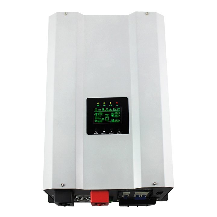
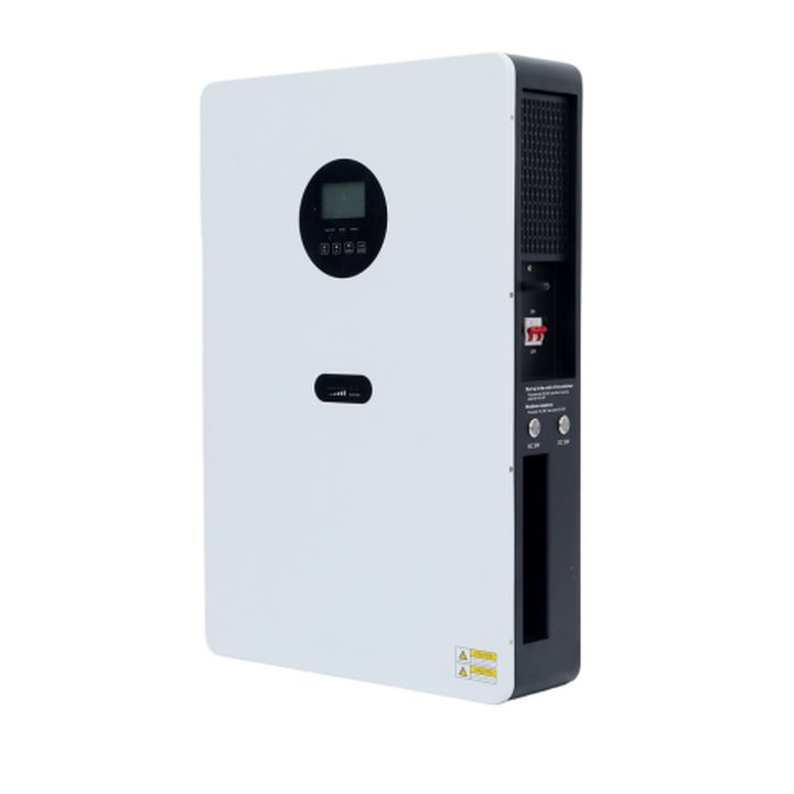
All-in-one solar system ESS 5KW Hybrid Solar inverter Integrated with LifePO4 battery 5KWH
5 kWLiFePO4